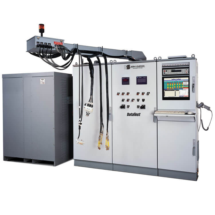
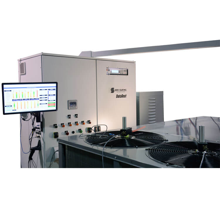
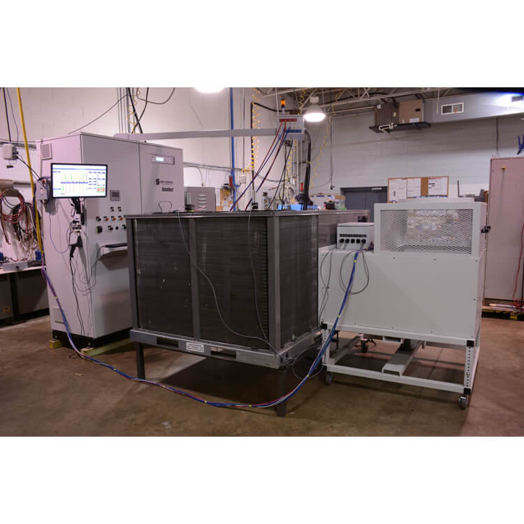
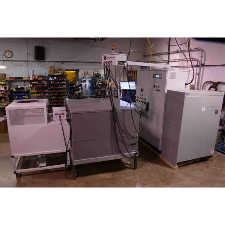
This system is designed to meet the needs of commercial system manufacturers whose products require startup loads exceeding 100 Amps. Testing sequences are typically more comprehensive and have a duration of 10-20 min. This system specializes in multi-circuit and custom testing requirements. Testing sequence can be paused while adjustments and corrections are made.
Cooling Mode:
Heating Mode (Heat Pump):
Heating Mode (Electrical Heat):
Heating Mode (Gas Furnace):
Idle State:
Defrost Board Operation:
Dehumidification Test
Vent Package Test:
Low Voltage Start:
UL Safety Test:
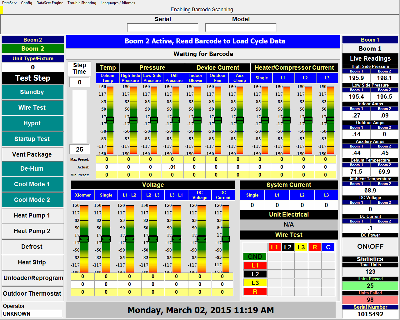
Wire Test:
Windings Test:
Low Ambient Controls:
Test Mode
Allows operator to apply voltage to unit and manipulate thermostat controls for troubleshooting purposes or to run pilot units to collect test values.
Service Mode
Allows Maintenance to operate and monitor individual components of the tester to verify operation, troubleshoot and perform PM.
Analog Sensor Calibration
Provides a simple means of verifying sensor operation and adjusting the readings to match a control source.
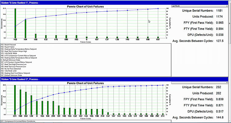
Station Performance Monitoring
Track testing results over an adjustable range including pass, fail, processed, first time yield, operator idle time, etc.
Operator Security
Insure only trained operators can operate the test station, track operator efficiency, prevent unauthorized and unsafe use.
Personalized Work Instructions and Messaging
Customize and adjust the work instructions to fit the nomenclature and culture of your work environment. You have complete control over wording, font, color and size.
Network and Remote Connectivity Monitoring and Troubleshooting
On screen notifications allow the operator to know if a problem has occured to the system connections.
Wireless Bar Code Readers Standard
Touchscreen Monitors Available
DIMENSIONS:
90″H x 134″W x 36″D
UTILITY REQUIREMENTS:
480V, 3Ø, 100A-200A
Download .pdf of this product
Ready to take the next step and learn more about what Serv-I-Quip can do and how we can help you with your business?